Single Loop DC Generator
Overview and Purpose
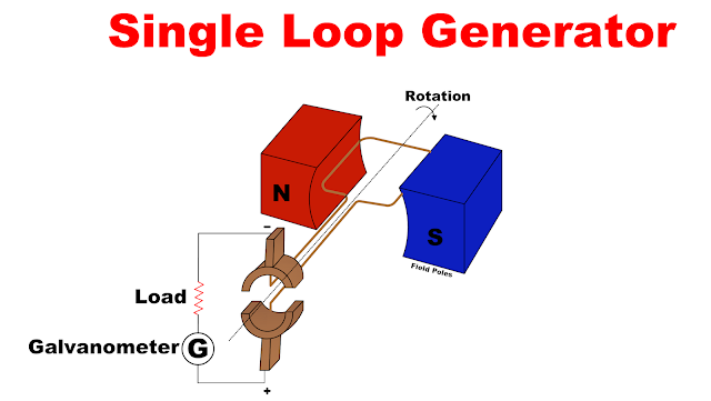
The single loop DC generator is the simplest conceptual DC machine: one rectangular turn (N=1) rotates in a magnetic field. While impractical for power production, it serves to illustrate electromagnetic induction, the role of the commutator, and how waveform shape depends on geometry. The model helps derive key relations later generalized to multi-turn armatures and real machines.
Detailed Construction
Key physical parts and their design notes:
- Armature (coil): A single rectangular loop rotating about an axis perpendicular to the magnetic field. Conductor placement and coil orientation determine the amplitude and sign of induced EMF.
- Field poles: Typically two poles (N and S). Field strength must be uniform across the active region for predictable EMF. Increasing pole face area reduces flux leakage.
- Commutator: A split ring that mechanically reverses coil connections every half turn, converting the intrinsically alternating coil EMF into a unidirectional (pulsating DC) terminal voltage. Contact timing, brush placement, and commutator segmentation determine the ripple content.
- Brushes: Stationary carbon or copper brushes press on commutator segments to extract current. Brush contact resistance and wear affect voltage drop and spark generation at reversal instants.
Electromagnetic Theory & Equations
Start from Faraday’s law for a moving conductor in a magnetic field. For a conductor of length l moving at velocity v perpendicular to a uniform flux density B, the instantaneous induced EMF is:
$$e(t) = B\,l\,v(t)$$
For rotation with angular speed ω and coil radius/geometry that relates linear velocity to ω, we can write the coil side velocity as v = ω r (or in terms of tangential speed at conductor). For a rectangular loop, the instantaneous EMF across a side moving perpendicular to B becomes:
Integrated over the whole loop and considering both sides (opposite signs when moving in reverse directions), the net coil EMF is sinusoidal (for ideal symmetry) and the commutator flips the polarity at the terminals. The average DC component over one mechanical revolution for a single-turn armature is proportional to flux per pole Φ and rotational speed n (rev/s):
$$E_{\mathrm{avg}} \propto N\,\Phi\,n$$
With N = 1 here. In practice, for multi-turn armatures with effective turns and winding distribution, the constant of proportionality includes geometry and coil pitch factors.
Waveform & Commutation
Without a commutator, the induced EMF in the loop is alternating and approximately sinusoidal (assuming uniform field and rotational motion). The commutator reverses the connection of the coil to the external circuit every half turn, producing a unidirectional but pulsating waveform at the terminals. For N=1, the pulsation is large — the terminal voltage drops to zero twice per revolution and reverses polarity internally, but the commutator corrects polarity at the output.
Important practical note: at the instant of reversal, brush contact may cause sparking unless the switching is synchronized with zero-crossing or proper interpoles/compensation is used (in practical machines).
Performance & Limitations
- Output quality: Very poor; high ripple and zero-crossing interruptions. Smoothing requires many parallel turns or external filters.
- Mechanical stress: Small models may tolerate single-loop arrangement; larger machines require distributed windings to balance forces and reduce vibration.
- Efficiency: Low due to small active conductor length and high relative commutation losses.
Derivations & Worked Example
Consider a rectangular loop of width w and effective radius r rotating at n rev/s in a uniform field B. The peak EMF magnitude from one side can be approximated by:
The time-varying EMF follows the cosine of the mechanical angle; the terminal waveform after commutation becomes a sequence of half-sine pulses. The RMS and DC average values are far lower than a multi-coil armature for the same speed and flux.
When and Why We Use the Model
Education: excellent for demonstrations on EM induction and for deriving relationships between flux, speed and induced voltage.
Design intuition: helps explain why many turns and distributed windings improve output smoothness, increase voltage, and reduce commutation issues.
References & Further Reading
- Textbook: Electrical Machinery — A clear chapter on DC machines.
- IEEE papers on commutation and interpole design for improved DC machine performance.